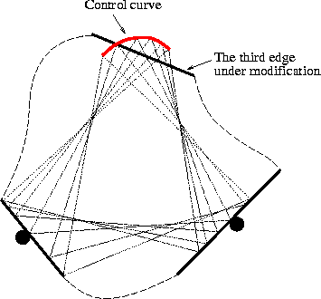
Figure 6: The third point contact can always be achieved
as long as the third edge intersects the control curve.
This contact locus enables us to design an interactive user interface to guide the process of part modification because the contact locus provides us a simple design rule: the third edge has to intersect the elliptic contact locus in the moving frame (Figure 6). Since the contact locus is quadratic, the intersection can be instantly verified.
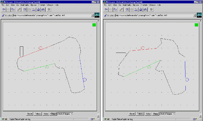
Figure 7: An initial part (left) and a modified part (right)
that share the same locator positions.
Our interface allows the user to select an edge to be manipulated. The user can move the entire edge or drag a vertex to change the part's shape. So long as the modified shape is compatible with the fixture, the display is updated in real-time. As soon as the edge no longer intersects the contact locus, the indicator on the upper right corner (figure 7) changes color to notify the user the violation of the design rule. Again, all of this processing is performed on the client without server interaction.
Figure 7 shows an example of design process. On the left, we show an initial part and its fixture. On the right, the part has been modified but still uses the same locators. Of course, the clamp position is different.